
MSI Z77A-GD65 Gaming Motherboard - The March of the Dragoon Army
The Z77A-GD65 Gaming is MSI's flagship Intel Z77 Express-based motherboard that is a nod to the gaming community. We check out how this gaming board performs as we put it through its paces!

March of the Dragoon Army
The information on this page is mostly from our preview article. For those who're familiar with the board, you can skip to our software features page and test results segment.
To any hardcore PC gamer, building a gaming rig is akin to tuning a sports car where every component is thoroughly scrutinized to ensure it packs the most horsepower for his hard-earned money. A well-tuned car is greater than the sum of its parts; however, at the heart of a high-performance gaming rig it doesn't hurt if a high-end motherboard is featured to ensure the rest of the components work together like the well-tuned sports car.

The MSI Z77A-GD65 Gaming board sports a menacing-looking chipset heatsink that sports the Dragoon Army motif. The board supports overclocked memory modules rated up to DDR3-3000+ and features a Killer E2205 Gigabit chip to reduce latency during online gaming.
Building on the success of its gaming series laptops, namely, the MSI GT70 and the MSI GT70 One, the company has launched the Z77A-GD65 Gaming as its flagship gaming motherboard aimed squarely at PC gamers and enthusiasts. The board bears the Dragoon Army motif that signifies membership to a group of elite fighters, according to MSI's official gaming site. Besides sporting such a fancy chipset heatsink, this standard ATX board is also chock-full of high-end features and supports LGA1155 processors. We also drew comparison to another MSI offering, the Big Bang Z77 MPower. Although they are very different in their appearance as well as their target market, they do share some similar features. So read on to uncover the details of the Z77A-GD65 Gaming board!
Triplet of PEG Slots
There are three PCIe Gen 3.0 x16 slots that support both but NVIDIA SLI and AMD CrossFireX multi-GPU setups. The board will support such setups only with the use of a third generation LGA 1155 processor. Like a typical LGA1155 board, it can only supply 16 PCIe lanes for these PEG slots; if the first slot is installed with a lone discrete graphics card, it will get to enjoy the full bandwidth of the 16 lanes. If the second slot is also installed with another card, the lanes would be even split between the two occupied PEG slots; with each slot allocated the bandwidth of 8 lanes. Once the gamer maxes out all the slots, the first PEG slot still enjoys the 8-lane bandwidth; however, the remaining pair has to share the leftover 8 lanes evenly. Hence, we did wish that MSI could have included a PLX PEX 8747 high speed switching chip that will effectively double the bandwidth to 32 lanes across all available PCIe Gen 3.0 x16 slots like the Gigabyte GA-Z77X-UP7!

Besides the three PCIe Gen 3.0 x 16 slots, there are also four PCIe 2.0 x1 slots. Like the Big Bang Z77 MPower board, there are no legacy PCI slots.
In that respect, we feel the board is a bit of a letdown when it comes to supporting high-end graphics card setups with enough bandwidth. Fortunately, a dual x8 configuration is more than enough for a good percentage of the gamers and enthusiasts. So instead of shoring up an expensive PLX switching chip to accommodate the small percentage of users who will actually use all the three PEG slots, MSI has opted to improve the board's features in other ways as we'll detail further.
Last but not least, take note that there are four PCIe 2.0 x1 slots but there are no legacy PCI ones. Hence, owners of old expansion cards like RAID adapters and sound cards might be disappointed, but it's also high time for users of these legacy devices to move on when upgrading to a new system.
Power Regulation
The MSI Z77A-GD65 Gaming board features Military Class III components that consist of Hi-c capacitors (Hi-C Cap), super ferrite chokes (SFC), along with DrMOS II and solid capacitors (Solid Caps). The CPU voltage regulation circuit sports twelve phases and with its Military Class III components for unadulterated, smooth power delivery for the processor, we expect this board to appeal to overclockers, especially with its support for overclocked memory modules that have been rated up to DDR3-3000+MHz.

The VRM heatsinks are sharp and may draw blood from the unsuspecting rig builder. There is a Super Pipe, essentially a 8mm thick heat-pipe, which connects the pair of heatsinks. We can also see the two rows of SFCs sit in front of the heatsinks.
To the right of the LGA1155 CPU socket, there are four DIMM slots; beyond the clips of the DIMM slots, near the edge of the board, there is a DrMOS alarm LED and eight CPU Phase LEDs. As mentioned earlier, the CPU has a total of 12 power phases for a reliable flow of power and these eight LEDs will light up to indicate the number of power phases in active operation; while the DrMOS alarm LED will light up when the MOSFET ICs have overheated.

It is rather cluttered at this edge of the board with two fan connectors located very close to the DrMOS and CPU Power Phase LEDs. At the adjacent edge, we see the three on-board buttons that are called Easy Button 3.
We have noted the awkward position of the onboard control buttons (Easy Button 3) as they will be inaccessible after the board is mounted inside a tower chassis with its optical disc drive (ODDs) in place. As we moved along the DIMM slots, away from the Easy Button 3, we see the voltage checkpoint connectors that are located near the ATX power connector.

Like the Big Bang Z77 MPower board, the voltage checkpoint connectors are positioned very close to the ATX power connector.
Other Features of the Board
Due to the presence of a third-party Asmedia ASM1061 SATA 6Gbps controller, there is an additional pair of such connectors on top of the default ones that are courtesy of the Intel Z77 chipset. The four SATA 3Gbps connectors are sandwiched between the two stacks of SATA 6Gbps ones on either side. To the far right, there is a front-facing USB 3.0 expansion connector that will make it easy to connect with the USB 3.0 I/O at the front panel of a tower chassis.

The rightmost SATA 6Gbps connector stack is driven by the board's Intel Z77 chipset; while the leftmost stack is powered by the Asmedia ASM1061 controller.
Moving behind the SATA connectors, there is the Multi-BIOS switch that controls the board's Multi-BIOS system to keep one BIOS chip for regular use and the other for back-up purposes. By flicking the switch left, it will toggle BIOS ROM A while BIOS ROM B is toggled when the switch is shifted right. The Multi-BIOS system is also used to perform BIOS recovery at the UEFI BIOS utility..

The Multi-BIOS switch is located near the edge of the heatsink of the chipset, behind the stack of SATA connectors.
At this edge of the board where the headers are located, we see a IEEE 1394 (FireWire) header that is located just before the USB expansion headers. This is due to the presence of a VIA VT6315N IEEE 1394 host controller chip.

From the left edge of the board are the front panel headers for audio, TPM, and system fan power connectors. The USB 2.0 and 3.0 expansion headers are to the right. They allow the connection of additional USB devices with their corresponding USB brackets (optional). With MSI's SuperCharger application installed on the operating system, these connectors will provide quicker USB charging.

The VIA VT6315N host controller chip that powers the IEEE 1394 expansion connector is located between the second and last PCIe x16 slots.
Rear I/O Ports
Next, we focused our attention on the rear I/O connectors. There is only a pair of USB 3.0 ports here as there are no third-party USB 3.0 controllers present. We also see the usually PS/2 keyboard/mouse gaming port (optimized for high polling rates) and four USB 2.0 ports (of which the two that are on the left most stack three times more gold than regular connectors for longer durability and prevents oxidization). Located next to that stack is the tiny, black clear CMOS button. The LAN port is powered by the board's Killer E2205 Gigabit chip. From our experience with the Killer Gaming network controller, we've found a slight tangible improvement in latency performance. Further to that, there is an onboard Realtek ALC898 audio chip that powers the audio options of the board with support for Creative Sound Blaster Cinema.

There are three video connectivity options in the form of the HDMI, DVI-D and VGA ports. For audio options, there are both coaxial and optical S/PDIF-out ports and six audio ports.

The Qualcomm Atheros Killer E2205 network controller that promises lower latency in online gaming.
As a testament of MSI's attention to details, we noticed that the rear I/O plate of the motherboard is coated in the colors of the Dragoon Army gaming series.

The letters and figures (in thin red outline) may be hard to read on the black background, but MSI spared no expense to ensure the consistent look-and-feel of its Dragoon Army gaming series is totally imbued in the motherboard.
Control Center
The Control Center is a dashboard to monitor and control the different settings of the Z77A-GD65 Gaming board. MSI has cleverly placed the overclocking tab as the default one when the Control Center loads. This proprietary tool is supported on Windows operating systems from Windows XP to the latest Windows 8 and is available on both 32- and 64-bit versions.

The Overclocking tab of the Control Center application is the default one when the application is launched.
It presents component information in a neat and organized manner; however, one of our main gripes with the color scheme is the red alphanumeric characters against the dark red background gradient makes them hard to read. Perhaps there should be options for users to turn off the colors of the Dragoon Army scheme and toggle to a color scheme that is more friendly to users with less-than-perfect eyesight.
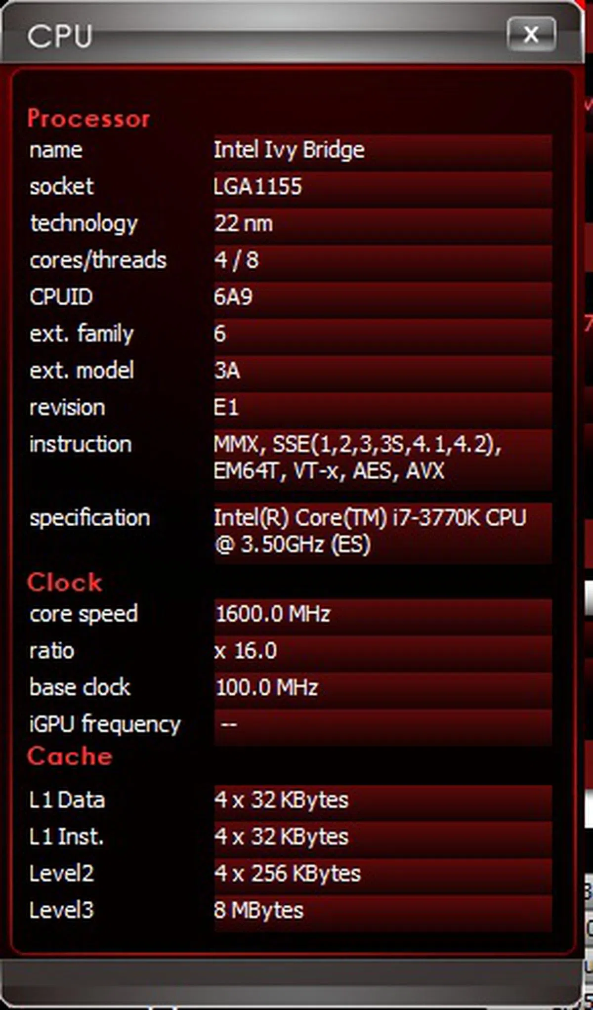 | 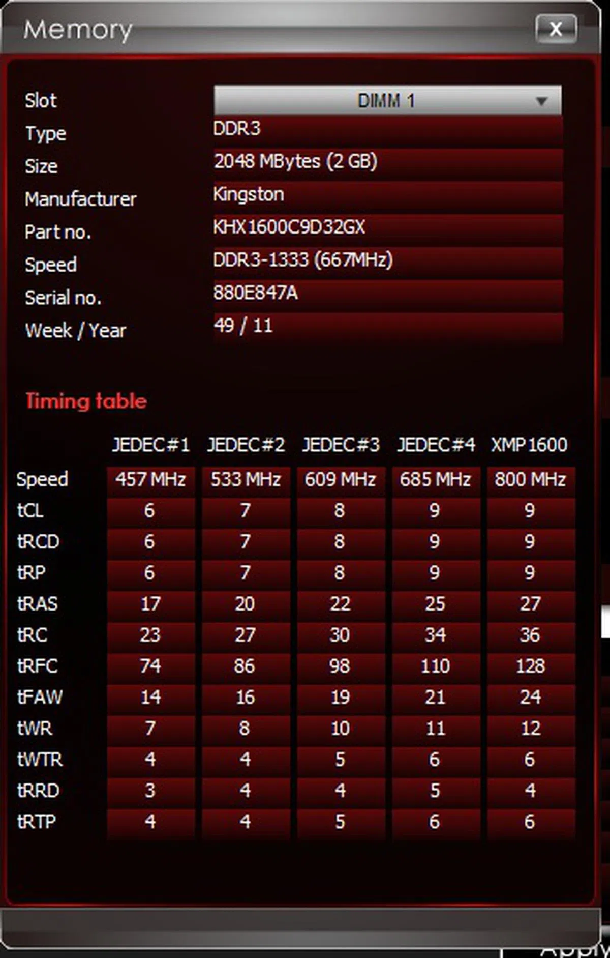 |
For fear of information overload, the detailed information of the CPU and memory modules can be accessed by clicking on their respective "More" buttons. In addition to present information, the Overclocking tab also allowed us to perform overclocking whereby in its corresponding section we could change the CPU ratio or the CPU base frequency with drop-down option boxes. For power users, there is also a DRAM timing section that is accessed by clicking the "DRAM Timing" button in the Memory section.
The Green Power tab gives options to set the fan speeds of the CPU and two system fans using a simple and intuitive interface. You'll also find a "CPU Phase Mode" control at the bottom left where you can control how many power phases are actively used for the CPU. More often than not, you're better off leaving it to the board's automatic algorithm.

We could change the fan speed profile by dragging the color points of the graph.

Besides using the color dots to change the fan speed profile on a graph, one can also use the text boxes for manual data entry to determine the fan speeds at different temperatures.
The LED tab, like the OC Genie tab, confounded us a little as the function we uncovered was to turn off the onboard CPU Power Phase LEDs. It is just a single function that makes it a notch more relevant than the OC Genie tab that was non-interactive and merely presented some information on the functions of the OC Genie feature. Even so, we don't really think this singular non-important control required its own tab and just adds to the tab clutter.

By clicking on the button, we managed to control the CPU Power Phase LEDs by turning them off or on, according to our whims.
The Record tab allows for real-time monitoring of system information with its graphical output; this is useful over overclockers and power users who need to keep a close watch on their preferred settings when they are tweaking their rigs.

The 'Record' label for this tab is a misnomer of sorts as there isn't any function to record the information displayed by the different graphs.
The Mobile Control tab allows the user to turn on the Command Center Remote Server and according to the software manual, this is only available for boards that feature the built-in Wi-Fi module; however, we were wondering if the system, with its LAN connection active, which is on the same subnet as the mobile device, installed with the Command Center application, will be accessible via its Remote Server service. We didn't have any luck trying it with a wired connection though. Overall, this feature is similar to the Gigabyte EasyTune Touch that we reviewed recently when we were testing the GA-Z77X-UP7 motherboard. More information of what the Mobile Control Center allows is captured in the screenshot below:-

The Command Center Remote Server service can be turned on here, allowing wireless access with a mobile device that has the Command Center application installed.
Click BIOS II
The Click BIOS II software can be accessed from the Control Center or from the shortcut that its installer places on the Windows desktop. Closely resembling the interface within the BIOS UEFI utility, it's main function is to literally access all the BIOS BIOS parameters from the Windows OS environment. This makes it an essential tool for power users to have unrestricted access to check and tweak all BIOS options from the Windows level.

The Click BIOS II software lets the user access most if not all the BIOS settings from the Windows OS environment.
After finalizing the tweaked settings, the software also enabled us to export the parameters' values into a configuration file that has a ".bd" file extension, which MSI has termed as the BIOSData. The file can be accessed and edited with any word editing software like Notepad or Wordpad. On top of changing the values of certain parameters, we could also enable or disable any of the onboard peripherals of the motherboard.

We clicked on the "Export" button to save our settings into a configuration file.

During our testing, we would usually disable certain onboard peripherals, so Click BIOS II was extremely useful as we could toggle them without having to reboot the machine to use the BIOS UEFI utility.
Killer Network Manager Control Panel
This software allowed us to monitor the network usage of different applications on our system. To reiterate, the MSI Z77A-GD65 Gaming motherboard features a that is an improvement over the previous Killer E2200.

This is the default section of the Killer Network Management application. Its most relevant section for gamers would be the Advanced section where the configuration of the network chipset is performed.
The Advanced tab would allow for network traffic prioritization, a highly prized option for online gamers who seek to reduce network latency for their gaming sessions.

The Advanced tab of the Killer Network Management application and its network traffic prioritization options.
BIOS Utility
The UEFI BIOS Utility of the MSI Z77A-GD65 Gaming has been given the Dragoon Army makeover to boost the red and black color scheme just like its Click BIOS II software access to the UEFI BIOS. However, in terms of layout and functionality, it is almost identical to that of the MSI Big Bang Z77 MPower.

The BIOS UEFI utility sports the color scheme of the Dragoon Army and we were thankful the alphanumeric characters weren't in red here!
Building on our observed voltage settings, we have added to the list, the various voltage settings of the Z77A-GD65 Gaming board that we modified in order to maintain its stable overclocked states. There were two ways to go about changing their values in the Windows environment by using the Control Center or the Click BIOS II applications; however, being creatures of habit, for our overclocking efforts with the MSI Z77 MPower, we decided to manually adjust the voltage of the CPU PLL to determine how high we can push the CPU Base Frequency. In the case of this particular board, base frequency values can be adjusted by 10KHz for finer tweaking.
Model | CPUVoltage | DRAMVoltage | Other Voltage Settings |
MSI Z77A-GD65 Gaming | 0.805 to 2.1550V
(0.005V steps) | 1.1080 to 2.4655V
(0.0015V steps) |
|
MSI Z77 MPower | 0.80 to 2.155V
(0.005V steps) | 1.1080 to 2.4655V
(0.0075V steps) |
|
ASRock Z77 Extreme6
| 0.80 to 2.20V (0.005Vsteps) | 1.17 to 1.80V
(0.005V steps) |
|
ASUSP8Z77-V Deluxe
| 0.80 to 1.99V
(0.005Vsteps) | 1.20 to 1.92V
(0.02V steps) |
|
Biostar TZ77XE4
| 1.000 V to 1.790V (0.01Vsteps) | 1.300 to 2.112V
(drop-down menu selection) |
|
ECS Z77H2-AX | 1.00 to 1.50V
(0.015V steps) | Voltage Offset:+0 to +0.63 V
(0.01V steps) |
|
Gigabyte GA-Z77X-UD5H WiFi
| 0.80 to 1.90V
(0.005V steps) | 1.17 to 1.80V
(0.005V steps) |
|
MSI Z77A-GD65 | 0.80 to 2.155V
(0.005V steps) | 1.10 to 2.10V
(0.005V steps) |
|
Test Setup
This is the test configuration for our Intel Z77 Express-based motherboard comparisons.
- Intel Core i7-3770K
- 2 x 2GB Kingston HyperX DDR3-1600 (CAS 9-9-9-27)
- MSI N460GTX Hawk (ForceWare 285.62)
- Western Digital Caviar Black 1TB SATA 6Gbps hard drive (one single NTFS partition)
- Windows 7 Ultimate 64-bit
- Intel INF 9.3.0.1020
Benchmarks
The following benchmarks were used to test the motherboards:
- BAPCo SYSmark 2007 Preview (ver 1.06)
- SPECviewperf 9.0
- Futuremark PCMark 7
- Futuremark 3DMark11 (ver 1.03)
- Far Cry 2
Results - SYSmark 2007 Preview
The MSI Z77A-GD65 Gaming was on par with the ASUS P8Z77-V Deluxe board, while coming in just slightly behind its OC counterpart, the MSI Z77 MPower. From its component scores, the board turned in strong performances on all the component tests.


Results - PCMark 7
From the overall score of the test, the MSI Gaming board is second and on par with the well balanced Gigabyte GA-Z77X-UD5H-WB WiFi mainstream performance board, easily making it one of the better boards in raw performance so far.


Results - SPECviewperf 9.0
The Z77A-GD65 Gaming's Pro/ENGINEER (proe-04) score was about a mere 0.5 per cent behind some of the leading high-end boards, else their scores would have been identical.

Results - Gaming
Its gaming performance was within our expectations; just trailing behind its OC counterpart by a very small margin.
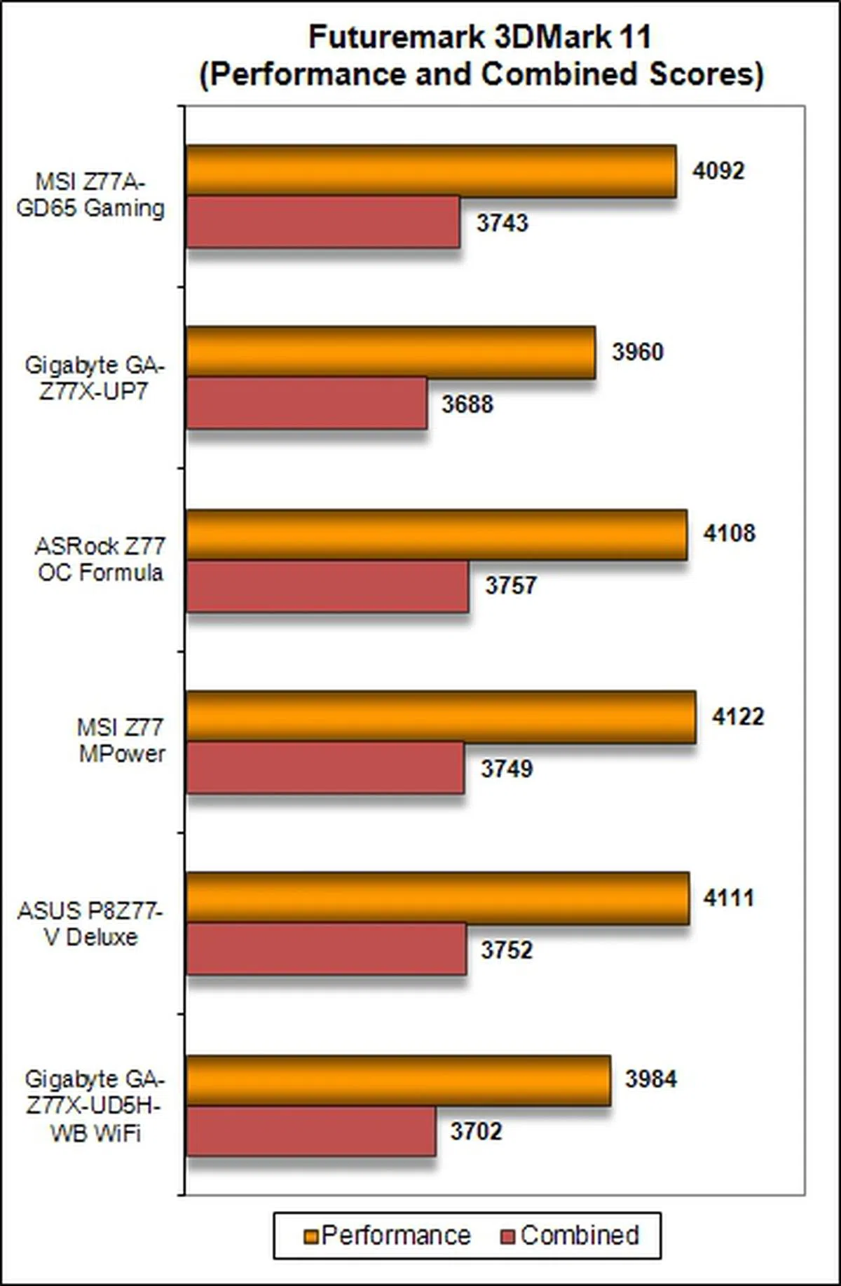 | 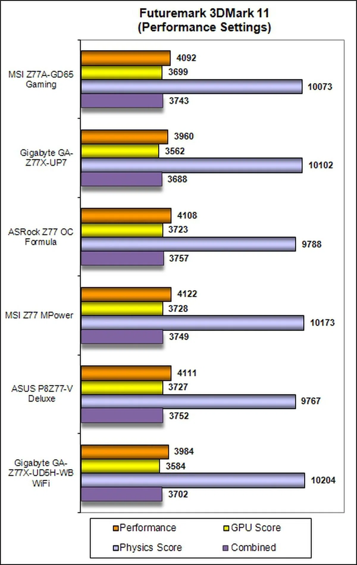 |

Temperature
The board's cooling system worked well and its operating temperatures were the second coolest we had recorded so far and it also fared a whole lot better than the mainstream performance Intel Z77 motherboards we tested last year.

Power Consumption
In terms of power draw, its performance mirrored that of the MSI Z77MPower with the same low idle power at 79W, and while under load, the MSI Z77A-GD65 Gaming drew 213W that was just two watts lower than the former board. Overall, that's pretty good given the components and features on this board against the rest of the compared boards and the mainstream Intel Z77 boards tested last year.

Overclocking
The MSI Z77A-GD65 Gaming was overclocked on three fronts. First, we tried to achieve the highest CPU Base Frequency by pushing it beyond the default value of 100MHz. At the same time, we kept the DRAM timings at the default values defined by the Intel XMP specifications that were compatible with our Kingston HyperX memory modules. We also set the DRAM voltages to around 1.65V to ensure system stability at the higher CPU base frequency. In order to ascertain the gains from overclocking, we recorded a baseline Cinebench (version 11.5) score of 7.91, with the board in its normal operational mode.
Highest CPU Base Frequency
By adjusting the CPU I/O Voltage to a value of 1.0700V while increasing the DRAM Voltage to a value of 1.6555V, the highest, and stable, CPU Base Frequency we achieved was 108.01MHz. We didn't manage to achieve anything useful from cranking the settings any higher. This put the board almost on par with its overclocked MSI compatriot. For the record, we strongly advise against doing this in the long run as it may risk damaging the CPU and the installed components due to the increased bus operating frequency. In this overclocked state, we recorded a Cinebench score of 8.30, which marked an increment of about 4.7 per cent.
Model | Maximum CPU Base Frequency Achieved
|
MSI Z77A-GD65 Gaming | 108.01MHz |
Gigabyte GA-Z77X-UP7 | 110.00MHZ |
ASRock Z77 OC Formula | 107.00MHz |
MSI Z77 MPower | 108.20MHz |
ASRock Z77 Extreme6
| 100.00MHz |
ASUS P8Z77-V Deluxe | 108.00MHz |
Biostar TZ77XE4 | 104.00MHz |
ECS Z77H2-AX
| 104.00MHz |
Gigabyte GA-Z77X-UD5H-WB WiFi
| 109.00MHz |
MSI Z77A-GD65 | 107.86MHz |
Highest CPU Core Ratio
In the second scenario, we attempted to achieve the highest CPU core ratio, while keeping the host CPU base frequency at 100HMz. We had to increase the CPU Core Voltage to 1.45000V, the CPU PLL to 1.8500V and kept the voltage settings for the memory modules at auto configuration. We managed to reach a stable OC state with the Gaming board achieving a maximum CPU Core Ratio of 47, with its CPU operating at a Turbo-boosted high of 4.7GHz! The board managed to achieve our highest (in this testing scenario) Cinebench score of 9.31, an increment of just over 15 per cent over the baseline score of 7.91.
Model | Maximum CPU Core Ratio Achieved
|
MSI Z77A-GD65 Gaming | 47 |
Gigabyte GA-Z77X-UP7 | 48 |
ASRock Z77 OC Formula | 45 |
MSIZ77 MPower | 44 |
ASRock Z77 Extreme6
| 43 |
ASUS P8Z77-V Deluxe | 45 |
Biostar TZ77XE4 | 45 |
ECS Z77H2-AX
| 45 |
Gigabyte GA-Z77X-UD5H-WB WiFi
| 44 |
MSI Z77A-GD65 | 45 |
Highest Overall Overclock
In the final overclocking scenario, we were unable to maintain a stable OC state once we pushed the CPU Base Frequency beyond 101MHz; as a result, we had to set it just slightly below at 100.90MHz. We also had to set the CPU PLL Voltage to a value of 1.8500V, and set both the Primary and Secondary Turbo Power Limit to the value of 500W. In the end, we managed to reach an overclocked frequency of 4.64GHz. Its Cinebench score of 9.16 marked a 13.6 per cent increment from our baseline score. Overall, the results obtained were commendable for a gaming oriented board.
Model | CPU Core Ratio | CPU Base Frequency (MHz) | Maximum Overclock Achieved
|
MSI Z77A-GD65 Gaming | 46 | 100.90 | 4.64GHz |
Gigabyte GA-Z77X-UP7 | 45 | 104.48 | 4.70GHz |
ASRock Z77 OC Formula | 45 | 101.00 | 4.54GHz |
MSI Z77 MPower | 43 | 101.00 | 4.34GHz |
ASRock Z77 Extreme6
| 43 | 100.00 | 4.30GHz |
ASUS P8Z77-V Deluxe | 44 | 103.80 | 4.56GHz |
Biostar TZ77XE4 | 43 | 103.85 | 4.47GHz |
ECS Z77H2-AX
| 45 | 103.50 | 4.65GHz |
Gigabyte GA-Z77X-UD5H-WB WiFi
| 45 | 103.00 | 4.63GHz |
MSI Z77A-GD65 | 41 | 100.98 | 4.14GHz |
Overclocking Experience
The parameter settings for the MSI Gaming board were sufficient and well laid-out for our overclocking efforts, and we would rank our experience with it as second to that when we were overclocked the ultra high-end Gigabyte GA-Z77X-UP7 board. Do note that the Gigabyte board was built for overclockers in mind while the MSI Z77A-GD65 Gaming board is targeted mainly at gamers. Overclockers and power users are also in the scope of MSI's target audience as the board boasts of Military Class II I VRM components as well as software utilities like fan speed control to regulate the temperature of the rig with both CPU and system fans. Hence, the board's overclocking features were definitely not designed as an afterthought.
From our experience, we would recommend that casual overclockers just adhering to the route of varying the values of the CPU Ratio as the performance gains eked out from increasing the CPU Base Frequency wasn't worth the risk of frying the components on the bus channel, especially the graphics card. We have also shown, in a limited empirical capacity as we only ran the Cinebench software for benchmarking OC gains, the performance gains by increasing both CPU Bus Frequency and CPU Ratio wasn't as high as the singular route of CPU Ratio adjustment.
Overclocking using OC Genie II
The OC Genie II is a one-touch overclocking system that MSI has implemented on its high-end boards. We had to power down the board, press the OC Genie II button and power up the board again.

The OC Genie button lighted up after we depressed it. This is truly a one-touch solution to overclocking the board!
The board managed to reach an overclocked state with the CPU Ratio increased to 42, and with no change to the CPU Base Frequency that remained at 100.00MHz. At a clockspeed of 4.20GHz, the board scored a value of 8.41 for the Cinebench application. This was an increment of almost six per cent over the baseline score.
Overclocking with Control Center and Click BIOS II
Our overclocking experience with the Control Center wasn't that smooth as we experienced system reboots that occurred out of the blue as we attempted to replicate the different parameter settings we had achieved during our raw overclocking exercise. We were grateful for the drop-down box implementation for most of the parameters as we could select the values easily with deft mouse clicks. After a few inexplicable reboots, we decided to throw in the towel. We concluded that the Control Center is useful for tweaking the system when it was already overclocked as starting from scratch in overclocking may just leave the user scratching his head due to the possibility of unexpected reboots.

The Advanced menu for the CPU section allowed us to tweak the CPU Ratio for each core in the Windows environment. This would be appreciated by overclockers in their relentless pursuit to push their rigs' performance limits.
Our experience with the Click BIOS II application was much smoother as its interface closely mirrored the BIOS UEFI Utility; however, we were unable to locate one parameter called the CPU Core Vdroop Offset that we tweaked during our raw overclocking exercise. Despite this missing parameter, we would strongly recommend using the Click BIOS II if we had to overclock the system from its default settings in the Windows environment, but we were still unable to escape the need to reboot the system after making certain parameter settings.

The reboot warning dialog of the Click BIOS II application.
Conclusion
The general performance of the MSI Z77A-GD65 Gaming motherboard was reasonably good as they were in line with our expectations of high-end Intel Z77 motherboards. From an aesthetic viewpoint, the board is attractive as it sports the red and black color scheme of MSI's gaming line, together with the Dragoon Army styling on the board's chipset heatsink. With reference to our overclocking experience, we figured that it was better to modify the CPU ratio settings, and its corresponding parameters values, in order to achieve the most performance gains in its overclocked state.
For the main target audience of gamers, they would be pleased to know that the board features the Killer E2200 Intelligent Networking Platform in the form of a Qualcomm Atheros Killer NIC E2205-B Gigabit controller chip. Based on our previous experience with it, this feature will certainly come in handy for reducing online gaming latency to a small degree.

The MSI Z77A-GD65 Gaming board is targeted squarely at gamers with its Killer Gigabit networking chip to reduce network latency while gaming. With support for overclocked DDR3-3000+ memory modules and its software utilities for system tweaking, overclockers and power users will definitely not feel left out of the party. Furthermore, the board has pretty good overall performance, including overclocking capabilities.
The bundled software in form of the Control Center and Click BIOS II were adequate and the latter did its job well; however, we felt that in order to differentiate the Gaming board from the rest, MSI should have included a Wi-Fi and Bluetooth networking module. This additional piece of hardware would have fully fleshed out the system control capabilities of the Control Center application.
In summary, the MSI Z77A-GD65 Gaming motherboard is meant for discerning gamers, and it sports sufficient features to keep overclockers and power users happy. Its price tag of S$329 makes it just slightly more expensive (by about S$30) than most high-end mainstream motherboards that are currently priced at around the S$300 mark or thereabout. As such, we felt that it is a small price to pay in order to own the flagship Intel Z77 gaming board from MSI that has good all round performance, usability, and features for its target user group.
Our articles may contain affiliate links. If you buy through these links, we may earn a small commission.